Panel
This is by far my favorite part of the project. Other than the paint job, the panel is one of the few areas in RV construction where you get exactly what you want ( or what you can afford :-) You start with a clean slate and have nothing but tradition ( the sacred 6 ) and all that hot new technology to entice you.
I decided from the get go to wire up an IFR panel after all the VFR work I did in my 8, I felt it was time I took the next step and learned how to fly in all sorts of weather. I have no real intention of doing hard IFR but sometimes it sneaks up on you when you least expect it so why not be prepared.
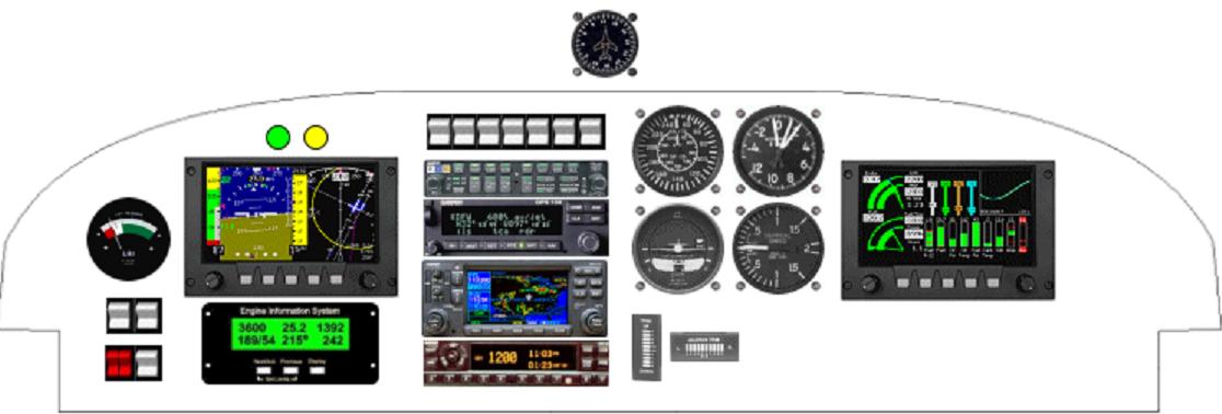
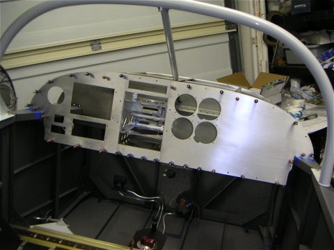
I started with Van's stock instrument panel and after running through about 20 different layouts the one you see above was my final choice. There is a cool article in one of the RVators where Van explains where the visual focus of the instrument panel is relative to the pilot. This has to do with a host of different variables including seat height, horizontal position of the pilot relative to the panel, and distance from the pilots head to the instrument panel. The net was that in a typical RV the pilot can easily scan an area about the size of your average dinner plate with the center being about 12 inches from the left most side of the panel and about 7 inches up from the bottom. Anything outside this area can be seen but not easily scanned.
After my second panel layout on my 8, I decided that I would try to make this panel easier to change after the fact. With the constant changing in technology and my penchant for the latest gadgets my 9 panel would have to consist of a small left sub panel and large right sub panel separated by a radio stack. Here again, leveraging my 8 experience, I placed a high value on the human factors element. I wanted my switches and radios to be close enough ( especially the Garmin 430 ) that I could easily utilize all the functionality without having to reach across the panel to do so.
While having the dual display GRT system located under the pilots nose would be cool, there are serious space limitations on the relatively small scan area so I decided that it was more important that the pilot have access to the radio stack from a communications and navigation perspective than an extra display. I expect that the added ease of updating flight plans in flight and screwing with changing transponder codes and VOR/Com frequencies will more than make up for the missing display. I may end up adding the Garmin HSI later as I have read that being able to use the Garmin HSI in conjunction with the GRT display makes for a powerful IFR platform. A dual axis Tru Track autopilot is also on my list for post first fight additions as this too is considered an asset to a comprehensive IFR package.
So.... out of the box I whipped out my saber saw and sliced and diced my stock Van's panel with the above layout in mind.
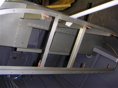
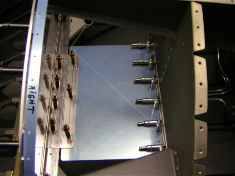
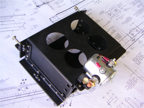
I also added a piece of heavy 0.125 angle across the bottom to give the frame structure. It's amazing how light and fragile that panel becomes when you remove that much material. I framed the avionics stack with two pieces of 0.063 angle to give the trays a place to mount. The entire structure is lined with #8 plate nuts for attachment of the 0.063 plates that will contain the avionics. You can also see from this picture that I had to remove a section of the forward bulkhead to accommodate the length of my 330 transponder and 430 GPS trays. I reinforced this area with 0.063 angle ( it's a good idea to buy several additional feet of this angle as you will use it both in your panel construction and your baffles when you get to the firewall forward work ).
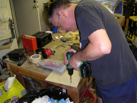
Here I am cutting out the left hand ( pilot scan ) side of the panel. As all almost all the openings on this side of the panel are square, I start by drilling all the corner holes large enough to accommodate the saber saw blade and use the saw to remove the bulk of the material. Then it's time to file, fit, file, fit.
The fly cutter, as you will find out for yourself, produces thousands of little shards of metal that fly everywhere ( hence the name and the need for safety glasses :-) It's also easy to bind the cutter if you put to much pressure on the drill press and so to keep from removing a few of my fingers when that happens, I gloved up. Liberal use of cutting oil during this process will help keep your cutter blade sharp and cut down on the ear splitting shrieking noise that the blade makes as it scrapes across that 0.063 aluminum panel. For all the mess, it's amazingly accurate and very easy to knock out the four holes I need to support my instruments.
Here is my cut out scotch brighted panel ready to paint and populate.
If you are a fuse vs braker proponent like me, you now face the quandary of where the heck to put the fuse panel. You need a location that is both easy to get to and relatively close to your instruments so your wire runs can be as short as possible. I decided on a location that was out of the pilots way but could still be reached by the pilot in flight in a pinch.
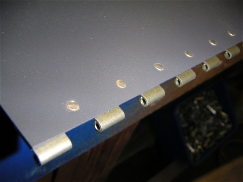
I went to the trouble to double flush rivet the rear hinge on so when the fuse panel is extended it will not interfere with bulkhead it's attached to and can lay flat for easy access to the fuses when in the open position.
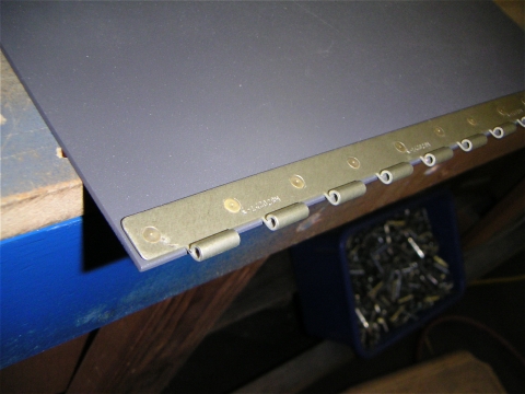
I also decided to use cam lock fasteners ( the same type used on the oil filler door ) for a strong mechanical connection when the door is up and locked in place. I had no interest in having the door drop down on my passengers legs while in flight so I used three fasteners for insurance. This design also had the added benefit of providing additional structural support to the panel as it no longer moved fore and aft when I pressed in the area that the throttle and prop controls would soon be mounted.
Here's the finished product.... as you can see the panel is split into two busses.
Essential Buss / Avionics Master ( diode protected dual feed )
Boost pump
340 Audio Panel
250 GPS Comm
430 GPS Comm Nav
330 Transponder
EFIS
AHARS
EIS
Turn Coordinator
Main Buss
Strobes
Nav Lights
Landing Lights
Heated Pitot
Tail Light
Trim Elevator
Trim Aileron
Flaps
Prime
Switch Panel lights
Avionics Buss Feed
Autopilot ( future )
Boost Pump with dual feed from both main and avionics master ( diode protected )
EIS with dual feed from both main and avionics master ( diode protected )
The essential buss will be fed from both the battery directly ( fused ) and from
the Main Buss with diode protection to keep from reverse feeding the main buss
when the essential buss only is turned on.
So...here's the drill, when you get in the aircraft you turn on the master. This will provide power to only the Master buss. You then start the engine. Once started you can turn on the avionics master, without getting into the big debate over how necessary this switch really is, for those of you that think it's a must ( your pretty happy right now ) and for those of you who think it's a waste of a switch ( write it off to ease of use since all my avionics can now be turned on at the same time with one switch :o) In the advent of an alternator failure, I can casually announce to the crew that we will be landing as soon as convenient while I flip the essential buss switch on and the master off. This gives me all the critical stuff just when I need it without having to screw with trying decide what's needed and what's not and go around flipping switches on and off. Ok... real life experience here... flying in my 8A with a new first time rider and my alternator takes a dirt nap, right after takeoff. POP goes the breaker. So.... guess what.... I'm freaking on the inside ( cool on the outside ) and immediately go into the MUST LAND NOW mode. Get back in the pattern and get back on to the ground. Truth is... I discovered in my own garage testing that I could have flown for another four hours before my battery would have even began to be a problem. So, moral of the story, have a plan, fly the plan, have fun.
It took me about two hours to finally decide on what should and should not be on my essential buss (deciding what should be "on" is the easy part, deciding what you can fly and land without, that's the challenging part). With all the cockpit loading that typically goes on in a busy pattern, I'm not going to get a blinding flash of insight and instantly know what should be hot and what should be not, so why not hardwire that in now while your building... capiche?
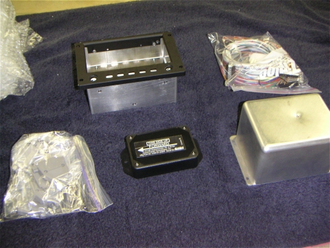
The lead time on that GRT stuff is around 8 weeks these days so they are kind enough to provide you with the option of purchasing a mock display case and an AHRS case. Using these mock cases you can cut your panel and mount the air data computer case prior to receiving your completed unit from the factory. This sample package runs about $150 for each case but it's totally refundable when you send it all back to the factory.
This is what I received from GRT... the package contains my magnetometer, the two sample cases, and the wiring harness. I'm only planning on mounting one display to start with but I went ahead and purchased the dual display harness on GRT's recommendation to make adding the second display a non issue when the time comes.
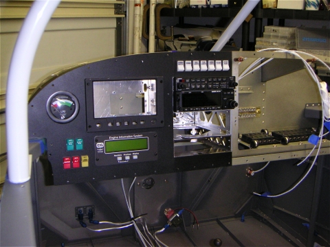
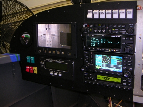
I took a little time off from work to make some headway on the panel last week and below is the result.
More on the switch panel...
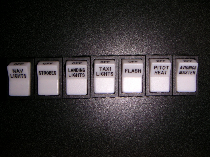
I purchased the switches at Allied Electronics. Here's the details:
(642-0131) AML34FBA4AC01 - Switch
(642-1060) AML91LA73 - Bulb ( yes they are lighted and they look great )
(642-5521) AML54-F10W - Cap ( white )
I got the caps and then sent them off to Aircraft Engravers. I later found out that Aircraft Engravers stocks the key caps so you can just email them your list of cap labels and they will mail you back the completed switch caps. They have several colors. This was not quick, so you should go ahead and get them on order as soon as possible if your going to go this route. Since the caps just snap off, you can go ahead and mount the switches prior to getting the caps.
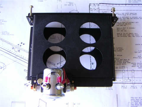
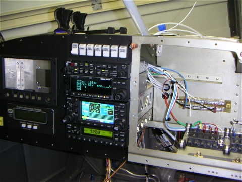
Now that I have all the major components in place it's time to start connecting the dots. First on this list will be to finish mounting the main contactor so that I can wire up the Master. Once I have power to the fuse panel, I can start with the intercom and work my way out from there. As you can see from this picture, I have the Garmin 340 audio panel and the backup Garmin 250 GPS mounted and ready for wiring. I'm expecting my GRT display around the first week in December so this should work out perfectly.
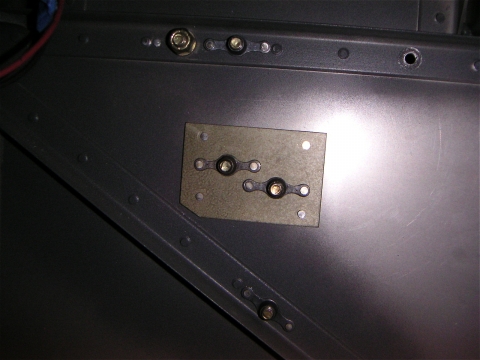
Starting from the battery, I installed the starter and battery contactor. This is a busy little task which involves lots of measuring and remeasuring to ensure that the right rivets are drilled out and everything lines up just right. Below is a shot of the little doubler that you have to make to reinforce the attachment points that are not supported by firewall angle. One thing I learned from this experience is that the larger the platenut the more important it is that you have a bolt holding the platenut in alignment with the structure your attaching it to before you do your riveting.
Here it is installed on the firewall primed and riveted in place.
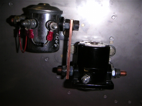
When bolting the contactors on to the firewall with the buss bar you pretty much have to do this all at the same time. Once the relays are bolted on, there is no way you can get that buss bar on after the fact. The fit is just to close. Here's a shot of the completed assembly.
Ok, now I have power...
Here's a few shots of my battery box for reference... I mounted an additional contactor on my box to support electric Bob's over voltage protection circuit ( I have an alternator with an internal regulator ) so I require a separate contactor to brake the circuit if the alternator breaks regulation and tries to fry all my expensive electronics...
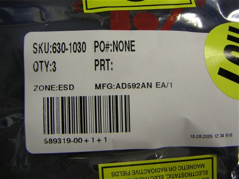
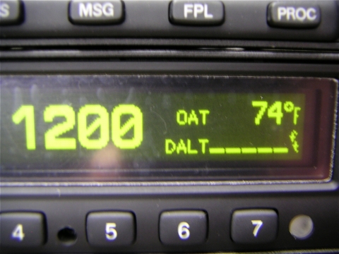
On to wiring up the stack. When hooking up my power to my Garmin 330 transponder I noticed that it could also use a temperature probe to compute on the fly the density altitude.... how cool is that. The probe part number ( a third party part ) was in the install manual so off I go to put on my procurements hat and order that bad boy. Well I called the distributor ( both of them actually - there are two listed ) after doing a quick web search and I get the same story from both, around $60 and you need to be a dealer to buy from us. So give me the name of a dealer in my area, and they did. Off I go to phone up the dealer and OOPS they don't have the probe "in stock"... well what's the lead time.... weeks you say.... maybe even months.... YIKES. So.... long story short, the Garmin install manual also gives you the specs on the probe ( 1 micro amp per degree K ). I google this and find several sources for a temperature sensor. So I ordered one from Allied $3.67.
and installed it...
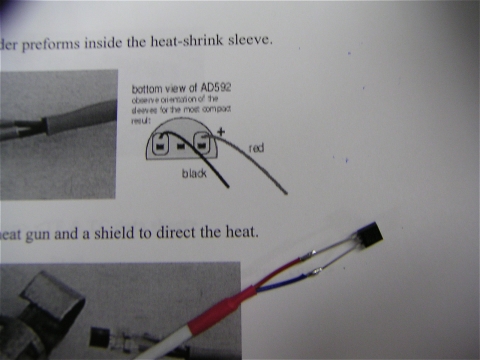
and it works like a hose.
So back to wiring my panel. I managed to get power to the stack. Boy this was much easier than I had anticipated. It took about two hours. Below is my avionics Christmas tree.
Having the fuse panel there so nice and close makes all these connections a snap.
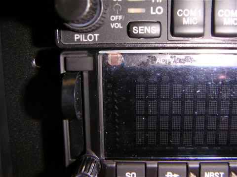
While I'm waiting on my EFIS and my engine hanging party, I decided to tackle the issue of lighting my switches. After looking closely at my stack I noticed that every instrument had it's own auto dimmer photo resistor ( up close it's pretty easy to see )
Sooooo why waste a perfectly good lighted switch to turn on the lights on the lighted switches??? Having that EE background was going to finally come in handy. Heck yeah, I'll just go out to ExpressPC and download the schematic capture tool ( which I did ), design a quick and dirty photo switch with relay ( which I also did ) and layout the circuit board ( which.... ). Head down to the local electronics store, let's see... I need one of those, six of these, two transistors, a relay.... let's see I'm up to about $25 in parts in my hand. I'm thinking... the minimum order from Express is 3 boards at a total of $69, and the parts I already have... wait a minute. What's this? I check out hobbytron and what do I see?
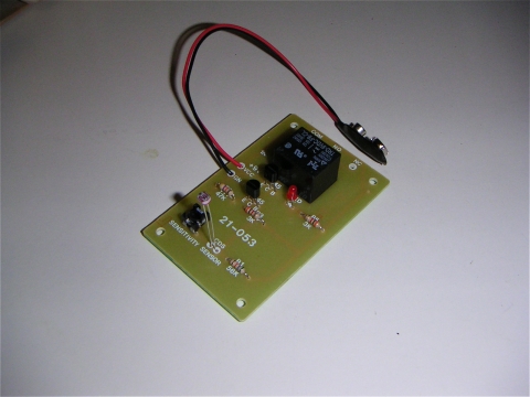
Total cost $8.95. The relay is good up to 10 amps. I should be able to squeak by on that. Total build time: 5 minutes ( ok, I already had a hot soldering iron ). Problem solved.
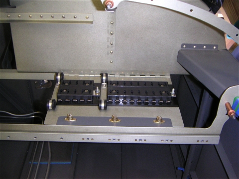
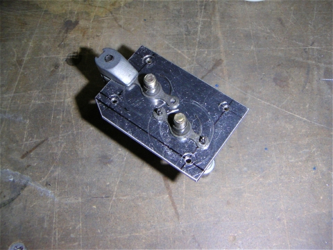
Next on the list, hook up those infinity grips and find a better way to tame all those trim and flap relay issues. In my 8 I had no less than 10 relays ( automotive ) and about 60 wires going from relays to trim motors to infinity grips. I don't have to paint you a picture. Not pretty. So this time around I decided to go a different and a little more compact route. First I purchase three relay boards from Aircraft Extras for $19 each. Compact little units that I can easily fit into a small enclosure. Here's the shot of the raw materials.
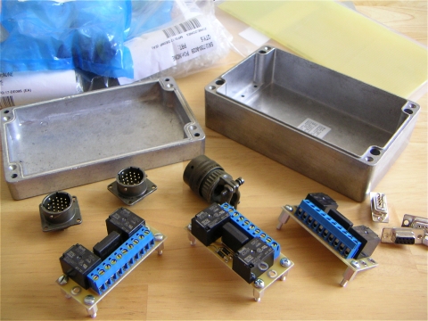
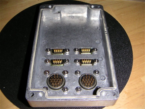
I picked up a box from Allied ( hey, what can I say, they have a warehouse in Texas ). It's water tight and fits nicely under the pilots seat.
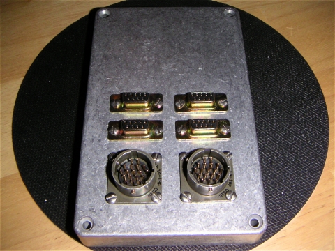
Next I get out the drill press and start carving up the lid to accommodate all the connectors. It turns out the infinity grips work really well with an 18 pin cannon connector which I picked up from ( Al... well you guessed it ). While I was at it I went ahead and picked up a set of inline cannon plugs so I could disconnect the passenger stick and remove it for those rare times when I'll be flying with a non pilot.
Here's the connectors all mounted and ready for wiring.